

Best Price Guaranteed

Microcontroller
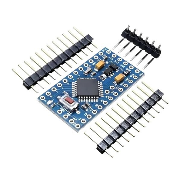
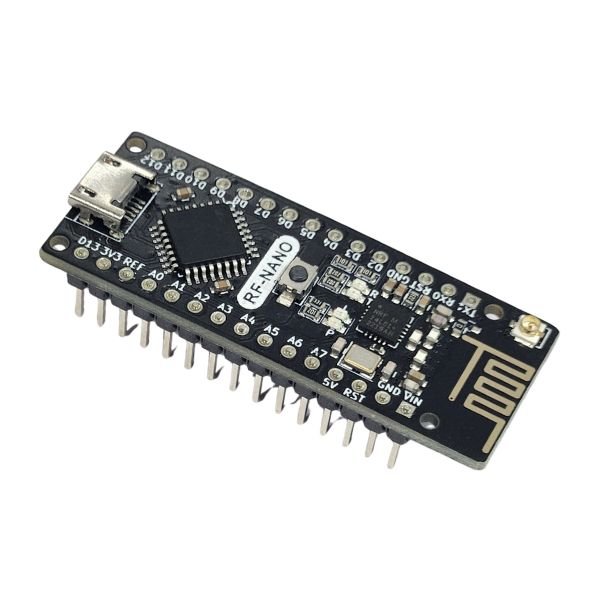
Arduino Pro Mini 5V 16MHz ATmega328P Compatible Board for Robotics & IoT
In stock
₹280.00 (Included GST)
SKU:
SV-DEV-AR009
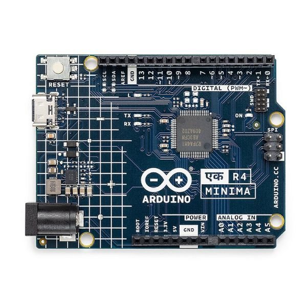
Official Arduino UNO EK (एक) R4 Minima – Made in India
In stock
₹800.00 (Included GST)
SKU:
SV-DEV-OA999

A2212 1800KV Brushless Motor for RC Airplanes and Quadcopters
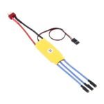
₹390.00 (Included GST)30A ESC for Brushless Motors in Drones and RC Planes
₹390.00 (Included GST)F450 F550 Drone Landing Skid – Tall Gear Set for Quadcopter Frames
₹170.00 (Included GST)Electronics Modules
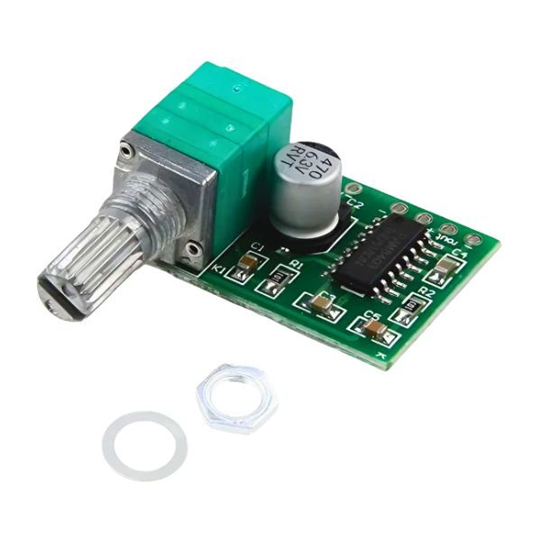
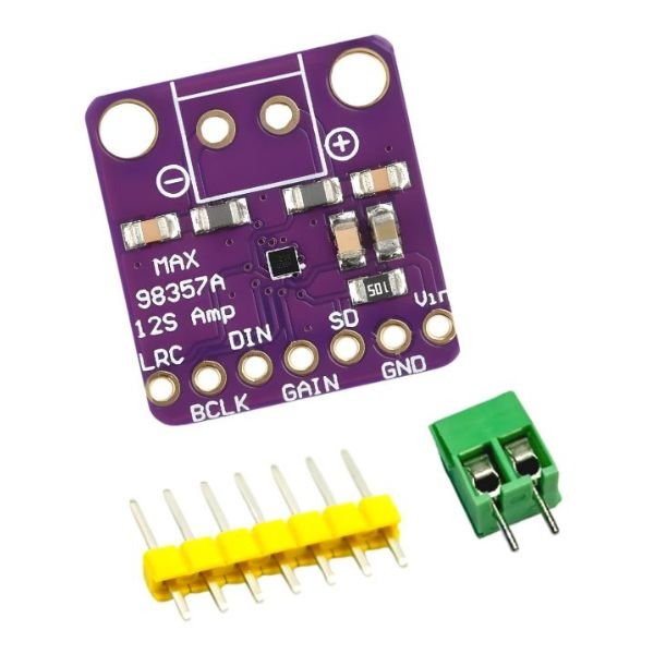
PAM8403 5V Mini Audio Amplifier Module with Volume Control
In stock
₹65.00 (Included GST)
SKU:
SV-ELM-AU075
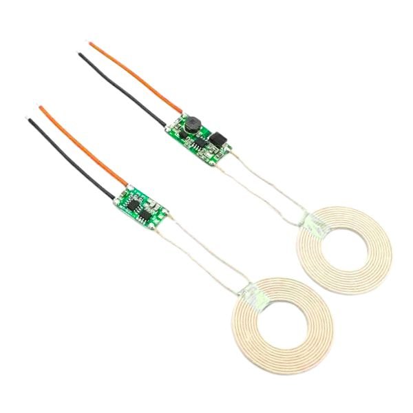
5V 2A Wireless Power Supply Transmitter Receiver Charging Module With Coil
In stock
₹750.00 (Included GST)
SKU:
SV-BAT-CP031
220V AC to 12V DC Converter Power Supply Board
Rated 4.36 out of 5
In stock
₹45.00 (Included GST)
SKU:
SV-ELM-PW015
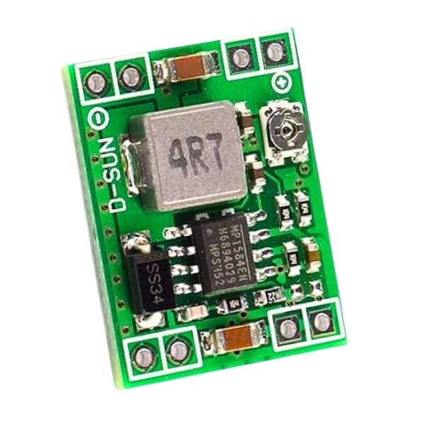
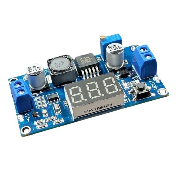
LM2596 Adjustable DC-DC Step Down Buck Converter Module
In stock
₹45.00 (Included GST)
SKU:
SV-ELM-PW005
15W Fast Wireless Charging Transmitter Module Type-CFor DIY Projects
Rated 4.71 out of 5
In stock
₹200.00 (Included GST)
SKU:
SV-BAT-CP035
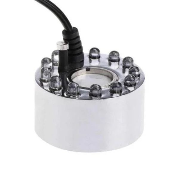
DC24V 20mm 12LED Ultrasonic Humidifier Mist Maker – Fogger Nebulizer
In stock
₹400.00 (Included GST)
SKU:
SV-SEN-HT021
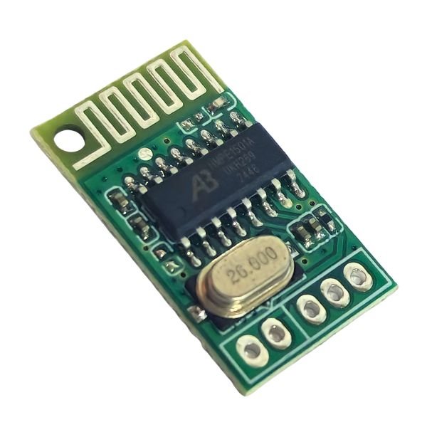
CA-6928 V2 Bluetooth Audio Module 5V
Rated 4.57 out of 5
In stock
₹80.00 (Included GST)
SKU:
SV-ELM-AU078
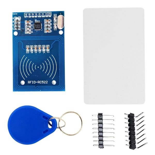
RC522 RFID Reader/Writer Module with RFID Card and Tag
In stock
₹75.00 (Included GST)
SKU:
SV-ELM-RF055
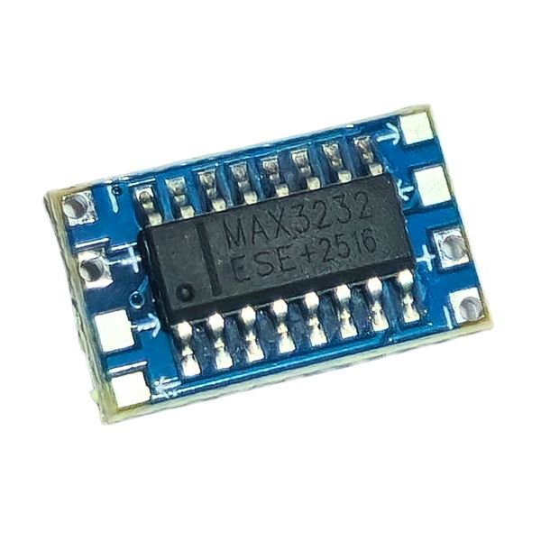
MAX3232 Mini RS232 to TTL Module Board
Rated 4.43 out of 5
In stock
₹30.00 (Included GST)
SKU:
SV-ELM-IN027
NE555 Delay Timer Switch 12V Relay Module (0-10 seconds)
Rated 4.36 out of 5
In stock
₹70.00 (Included GST)
SKU:
SV-ELM-RL010
TEC1-12706 Thermoelectric Cooler Peltier Module – 12V DC
In stock
₹200.00 (Included GST)
SKU:
SV-SEN-HT034
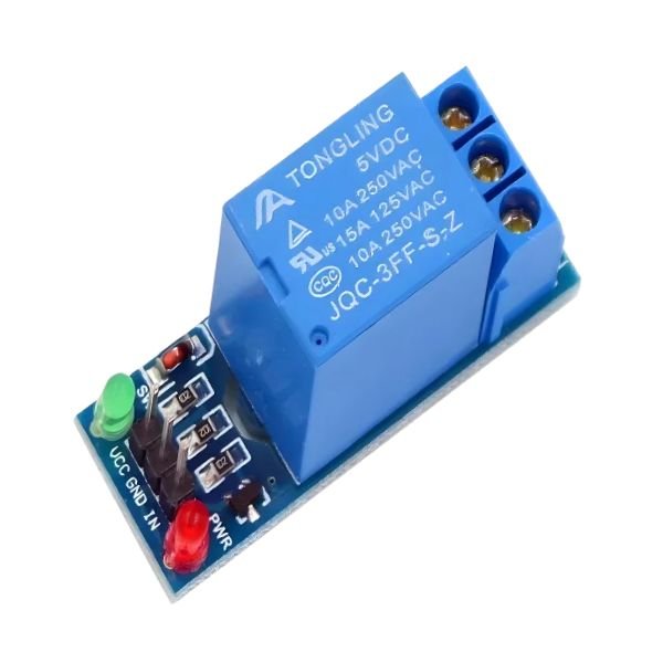
6–30V Single Channel Power Relay Module with Adjustable Timer
Rated 4.36 out of 5
In stock
₹125.00 (Included GST)
SKU:
SV-ELM-RL011
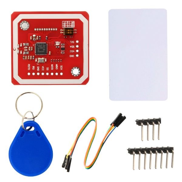
PN532 NFC RFID Reader/Writer Module V3 Kit 13.56MHz
In stock
₹290.00 (Included GST)
SKU:
SV-ELM-RF051
EM-18 RFID Reader Module 125kHz
Rated 4.43 out of 5
In stock
₹310.00 (Included GST)
SKU:
SV-ELM-RF056
12V 5A SMPS AC to DC Power Supply
Rated 4.43 out of 5
In stock
₹500.00 (Included GST)
SKU:
SV-BAT-CP034
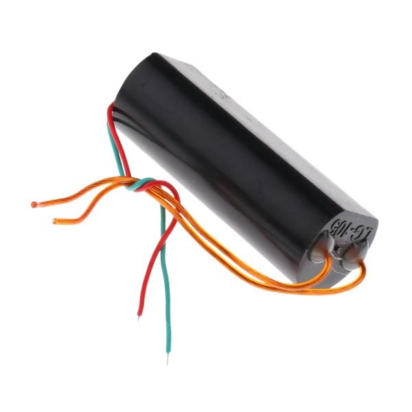
DC 3.7V to 400KV Step up Power Module High Voltage Generator
In stock
₹150.00 (Included GST)
SKU:
SV-ELM-PW013
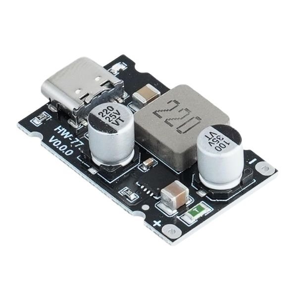
Fast Charging Module PD65W – C Type
Rated 4.64 out of 5
In stock
₹125.00 (Included GST)
SKU:
SV-BAT-CP029
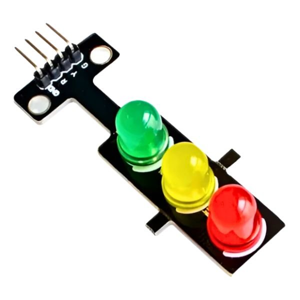
LED Traffic Light Signal Module with Digital Output
In stock
₹45.00 (Included GST)
SKU:
SV-SEN-LM011
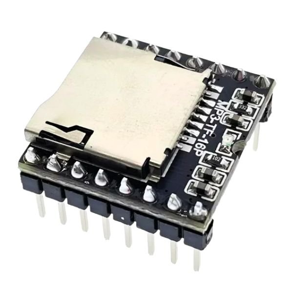
DF Player Mini MP3 Player Module With Serial Port For Arduino
In stock
₹85.00 (Included GST)
SKU:
SV-ELM-AU071
2S-2A Step-Up Boost Lithium Battery Charger Module 8.4V – Type C
In stock
₹70.00 (Included GST)
SKU:
SV-BAT-CP026
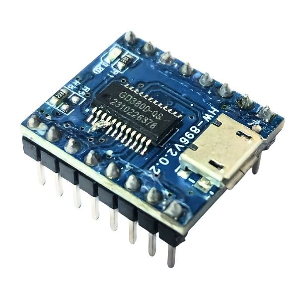
JQ6500 MP3 Audio Sound Player Module (16Mbit Storage)
Rated 4.57 out of 5
In stock
₹200.00 (Included GST)
SKU:
SV-ELM-AU077
Bluetooth 3.0 Audio Receiver Module with Stereo Output
In stock
₹70.00 (Included GST)
SKU:
SV-ELM-AU074
XH-M131 DC Light Control Switch Photoresistor Relay Module
Rated 4.43 out of 5
In stock
₹100.00 (Included GST)
SKU:
SV-ELM-RL012
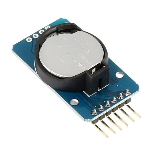
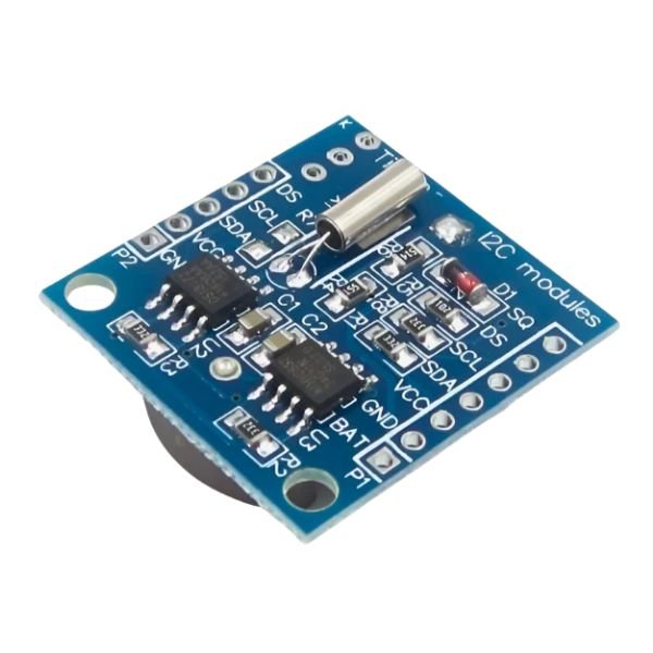
DS3231 RTC Module Precise Real Time Clock I2C AT24C32
In stock
₹135.00 (Included GST)
SKU:
SV-ELM-RT091
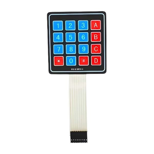
4×4 Matrix 16-Key Membrane Switch Keypad with Soft Touch
In stock
₹50.00 (Included GST)
SKU:
SV-ELM-KE001
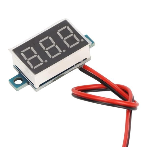
CellMeter-7 Digital Battery Capacity Checker for LiPo, Li-ion, NiMH Packs
Rated 4.43 out of 5
In stock
SKU:
SV-BAT-CP032
4×4 Matrix 16 Key Keypad Module
Rated 4.43 out of 5
In stock
₹55.00 (Included GST)
SKU:
SV-ELM-KE002
USB-C PD Trigger Decoy Module with Selectable Voltage Output
Rated 4.50 out of 5
In stock
₹110.00 (Included GST)
SKU:
SV-BAT-CP030
1000 KV High Voltage Booster Module
Rated 4.64 out of 5
In stock
SKU:
SV-ELM-PW014
220V AC to 5V DC Converter Power Supply Board
Rated 4.50 out of 5
In stock
₹45.00 (Included GST)
SKU:
SV-ELM-PW016
ZB2L3 18650 Li-ion Lithium Battery Capacity Tester Module Board
Rated 4.64 out of 5
In stock
SKU:
SV-BAT-CP033
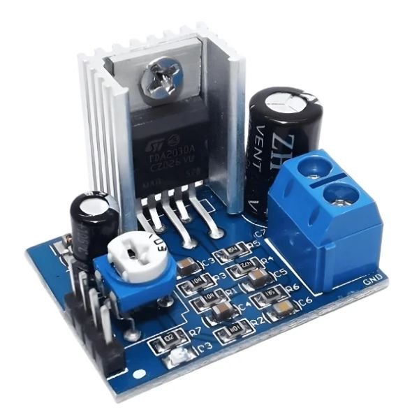
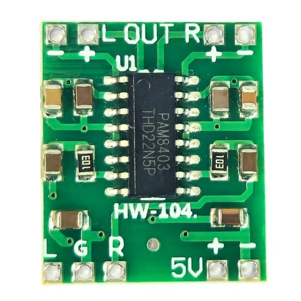
PAM8403 5V Two Channel Stereo Audio Amplifier Module HW-104
In stock
₹30.00 (Included GST)
SKU:
SV-ELM-AU073
3S-4A Step-Up Boost Lithium Battery Charger Module 12.6V – Type C
In stock
₹70.00 (Included GST)
SKU:
SV-BAT-CP025
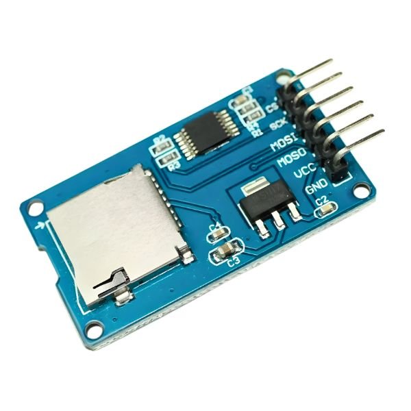
Mini Micro SD Card Reader Module
Rated 4.64 out of 5
In stock
₹25.00 (Included GST)
SKU:
SV-ELM-AU079
USB to RS485 TTL Serial Converter Adapter FT232 Module
In stock
₹190.00 (Included GST)
SKU:
SV-ELM-IN024
Stem DIY Kits
Fisher Scientific 10140 Indicator Papers-Full Range (pH 1.0 To 14.0)- 10 Bks (200 Strips)
In stock
SKU:
SV-DIY-SE003
Wooden Aircraft DIY Kit for Kids STEM Learning & School Projects
In stock
₹160.00 (Included GST)
SKU:
SV-DIY-SH012

Motors & Drivers
Powering Your Projects with High Torque Precision.


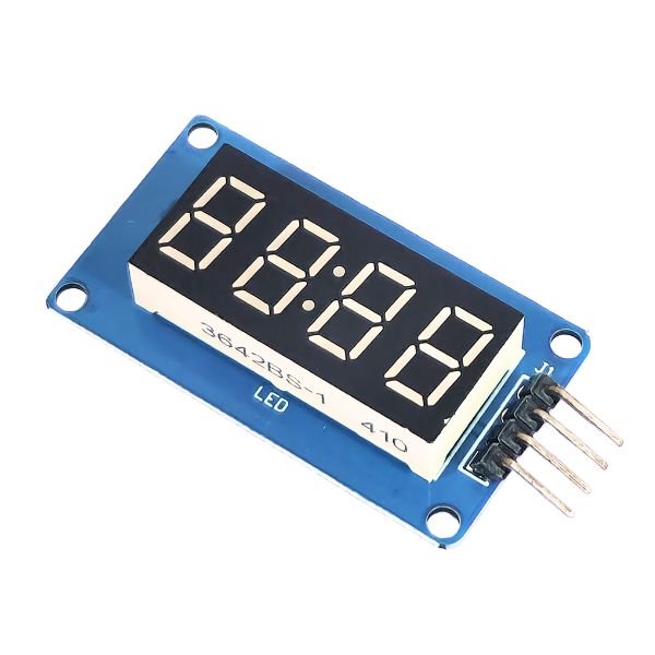
TM1637 4-Digit LED Display Module Red
Rated 4.71 out of 5
In stock
₹50.00 (Included GST)
SKU:
SV-DPM-DI017
Best Science Fair Projects Using Electronic Components
Best Science Fair Projects Using Electronic Components
Science fairs are exciting opportunities for students ...
HC-SR04 Ultrasonic Sensor
Complete Guide: How to Use HC-SR04 Ultrasonic Sensor with Arduino | StemvoltIntroductionThe HC-SR04 Ultrasonic...
Line Follower Robot Car with Arduino
Line Follower Robot Car with Arduino – Easy DIY Project GuideIntroductionLooking for a simple yet exciting Ard...
Top 10 Arduino Projects for Beginners in 2026 | Easy DIY Robotics Ideas
Introduction
If you are a beginner in electronics, robotics, or programming, the best way to start your journ...
EXCELLENTTrustindex verifies that the original source of the review is Google. I am Buy Best quality electronic components like capacitor, resister, 5mm leds , IC 555 , atmega8 A, diodes, soler penals, speaker, transistor, dc adapter and ac to dc power supply module at best prices in kota rajasthan Now available wide range electronic components for your every DIY electronic projects, Robotics school & college projects needs. Visit Now best electronic components, Robotics store all maker inventors and hobbies tic students in kota, rajasthanPosted onTrustindex verifies that the original source of the review is Google. Very good quality products in good prices all robotics or electronic items are available in this shop please visit once time ☺️Posted onTrustindex verifies that the original source of the review is Google. Good service and reasonable pricePosted onTrustindex verifies that the original source of the review is Google. All type of project material are available and good thakintive shopkeeperPosted onTrustindex verifies that the original source of the review is Google. got every parts in best pricePosted onTrustindex verifies that the original source of the review is Google. “Stemvolt is a reliable store for robotics and school project materials. They offer good-quality components at fair prices, and their staff provides helpful guidance for beginners. The product range is impressive, and orders are handled smoothly. A great place for students and makers looking for trusted project supplies.”Posted onTrustindex verifies that the original source of the review is Google. I am buy robotics parts electronic diy components at best from stemvolt diy storePosted onTrustindex verifies that the original source of the review is Google. Robotic projects available at good priceVerified by TrustindexTrustindex verified badge is the Universal Symbol of Trust. Only the greatest companies can get the verified badge who has a review score above 4.5, based on customer reviews over the past 12 months. Read more
- Subscribe to our Newsletter


